
Member Knowledge Centre
 member Knowledge centre
The Knowledge Centre provides CHBA members with access to information and resources. It is a growing resource that is currently focused on updating members about national building code information. Please note that this information is a benefit of your membership, and should not be shared beyond your company/organization.
You can browse the items below, filter by category, or enter search terms in the "What are you looking for" box below.
This information is provided by CHBA for informational purposes only and cannot be used as an official or authoritative document.
Understanding the New Lateral Load Requirements

Understanding the New Lateral Load Requirements
Updates in the 2025 Codes

Understanding the New Lateral Load Requirements
 Since the 2010 edition, the National Building Code (NBC) has had requirements for the resistance to lateral loads for homes in regions with high wind- and earthquake loads. The 2025 NBC will require all homes across Canada to resist lateral forces because low-wind and earthquake load locations will no longer be exempt. By mid 2027, the 2025 Harmonized National Construction Codes are expected to be adopted by all provinces. This means all homes in Canada will have to meet the new bracing requirements – mostly because of wind loads and not seismic loads!
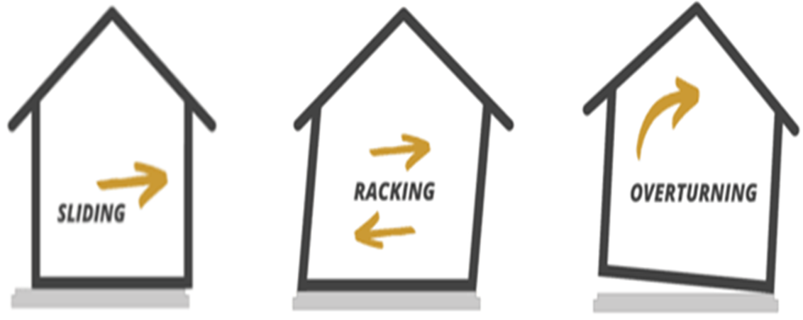
The lateral load requirements improve the structural resilience against wind and earthquake loads and became necessary because of the continued trend in home designs featuring open floor plans, large windows, and few interior walls, all of which reduce a home s resistance to lateral forces. The goal of these changes is to help ensure that buildings can better withstand wind and earthquake forces that might otherwise lead to racking or even collapse of walls during extreme events.
Technical Concepts
The new requirements revolve around technical concepts that already exist in current building codes, but the triggers that make these requirements mandatory currently exclude many regions of Canada. Where and how the technical concepts play a role depends on the type of compliance method chosen and on the local seismic and wind loads.
Braced Wall Bands (BWB)Braced wall bands are three-dimensional imaginary zones throughout a | 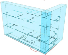 |
Braced Wall Panels (BWP)Braced wall panels consist of a wall assembly (sheathed with gypsum | 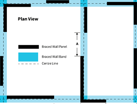 |
Seismic Design Parameter
The seismic hazard at a building site is represented by a value that reflects how much the ground is expected to shake during an earthquake. It is called Seismic Design Parameter, Smax , and can found using CHBA s online tool. Eventually the values can be found in Table C-3 of the 2025 National Building Code (NBC) as well. The Smax value with an unknown site class represents a worst-case scenario and the maximum value of Smax between all site classes. Better site class values can be determined using formulas and online tools or with the help of a professional.
Reference Hourly Wind Pressure
Hourly Wind Pressure (HWP) represents the design wind load a building must be designed to resist. It is derived from long-term weather data and, for lateral load design, corresponds to the annual maximum of hourly wind pressures from wind events in that location within a 500-year period (HWP1/500). HWP 1/500 values can eventually be found in Table C-2 in the 2025 NBC. Dividing the HWP1/500 value by 1.4 creates the Reference Hourly Wind Pressure (RHWP). Until the 2025 NBC is published with the finalized data, these calculated values can be estimated using CHBA s online tool.
Specified Snow Load
The specified snow load is a calculated value based on climatic data for snow loads. This value is required to determine if the Table Method (see below) can be used. The 2025 NBC will include snow load data updated to a 1-in-1000-year return period. All updated snow load values can eventually be found in Table C-2 in the 2025 NBC. Until then, calculated snow loads for each location are available on the CHBA online tool.
Compliance Methods
To meet the lateral bracing requirements, builders can choose from three different compliance methods in Part 9, each offering varying levels of simplicity and flexibility:
- Simplified Method - small, compact wood-frame homes can make use of an exemption based on very conservative design assumptions.
- Table Method - showing the minimum required length of Braced Wall Panels in Braced Wall Bands for each storey of a home after a builder selects the number of storeys and their sheathing method.
- Calculation Method - The most flexible method in Part 9 of the NBC taking local climatic data into consideration using detailed factors and look-up tables to determine acceptable design options (e.g. minimum required length of bracing).
Note: Where the limits for this method are exceeded, structural design according to NBC Part 4 is required, which is the most flexible method in the NBC.
Simplified Method
The Simplified Method can only be used in limited cases:
- The first case is a two-storey building with a length-to-width ratio under 2.2 with wood sheathed exterior walls with gypsum board on the interior face (refer to WSP-B in Table 9.23.3.5.-C).
- The second case is a one-storey building with a length-to-width ratio under 1.5, that cannot have a tile roof, stucco walls or floors with concrete topping, and is not clad with directly applied heavyweight material (i.e. normal-weight construction). Exterior walls are constructed using gypsum board sheathed wall panels (refer to GWB-C in Table 9.23.3.5.-C).
Additionally, and in both cases, homes must meet all requirements in the table below:
Requirements | Value | Details |
Seismic Hazard (Smax) | ≤ 0.47 | This applies to all locations in Table C-3 of the 2025 NBC (the values can also found in the CHBA online tool). |
Wind Pressure (RHWP) | ≤ 0.6 kPa, | This applies to all locations in Table C-2 Rough terrain is defined as suburban, urban or wooded terrain extending upwind from the building uninterrupted for at least 1 km |
Maximum Plan Dimension | ≤ 10.6 m | The building plan fits into a square of 10.6m x 10.6m |
Max. Wall Height unsupported | ≤ 3.1 | The maximum height that a wall can be built without requiring additional structural support like sheathing or bracing |
Roof Eave-to-Ridge Height | ≤ 3 m | Maximal projected height from eave to ridge |
Openings | <750 mm apart is treated as one | If openings, such as fenestration, have a separation of less than 750 mm between one another they will be treated as one opening |
Total Width of Openings per Side | ≤ 30% of wall length. | This refers to the total width of openings such as those from fenestration. If wall has >30%, whole house side uses Table Method. |
Maximum Width of Single Opening | ≤ 2.4 m | This refers to the maximum width of an opening such as a 2.4 m wide window |
After determining that the design and site conditions are eligible for the simplified bracing method, Table 9.23.3.5-C from the 2025 NBC (which currently only exists in the proposed change form) is used to determine the wall sheathing requirements based on the framing assembly type.
Example for Simplified Method
For this example, a two-storey house is being constructed with WSP-B in a rough terrain area in Athabasca, Alberta. The site class is unknown. Using the appendix tables, the seismic and wind parameters are taken as Smax = 0.151 and HWP1/500 = 0.59. RHWP can now be calculated by dividing 0.59 by 1.4, yielding a value of 0.421.
This confirms that the example home is eligible to use the Simplified Method and we can use Table 2025 NBC - 9.23.3.5.-C to determine the fastening requirements for the wall panels.
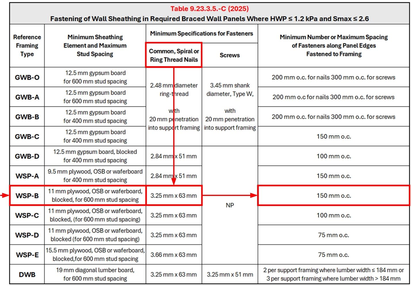
Table Method
The Table Method has to be used for every wall face of a building where the total width of openings in an exterior wall exceeds 30% and must meet the following requirements:
- The BW Panel must be constructed with gypsum on at least one side
- The BW Band must have continuous sheathing (gypsum board or wood)
- No tile roofs, stucco walls or floors with concrete topping, or clad with directly applied heavyweight material. Option for 1 face of masonry veneer.
Additionally, homes must meet all requirements in the table below:
Requirements | Value | Details | |
Seismic Hazard (Smax) | ≤ 0.47 | This applies to all locations in Table C-3 or found in the CHBA online tool. | |
Wind Pressure (RHWP) | ≤ 0.6 kPa, rough terrain | This applies to all locations in Table C-2 Rough terrain is defined as suburban, urban or wooded terrain extending upwind from the building uninterrupted for at least 1 km | |
Roof snow load | ≤ 2 kPa | Value can be calculated as using the Ss and Sr values found in Table C-2 of 2025 or found in the CHBA online tool. | |
Max. Plan Dimension | ≤ 21.2 m | The building plan has to fit into a square of 21.2 m x 21.2 m | |
Eave-to-Ridge Height | ≤ 3 m | Maximal projected height from eave to ridge | |
After determining that the design and site conditions are eligible for using the Table Method, Tables 9.23.13.8.-A to Table 9.23.13.8.-D in the 2025 NBC are used to determine the minimum total length of braced wall panels within a braced wall band. These tables all determine the minimum total length of braced wall panels based on what is being supported by the storey being designed. Which of the tables (A to D) is the correct one, will depend on the Smax and HWP value for the site.
Example for Table Method
For this example, a three-storey house is being constructed with WSP-A in a rough terrain area in Port Elgin, Ontario. The site class is unknown and the width of the roof is less than 4.3 m. Using Appendix Table C-2 and C-3 from 2025 NBC, the parameters are taken as Smax = 0.243 and HWP1/500 = 0.8, Ss,1/1000 = 4, Sr, 1/1000 = 0.6. RHWP is calculated as 0.571 (see above) and the specified snow load, S, is taken as 1.6 (see above).
The values of Smax and RHWP determine which table needs to be used. In this case it is Table 9.23.13.8.-B shown below because RHWP is less than 0.6 kPa and the Smax is less than 0.47.
The wall assembly used in this example is called WSP-A.
We use the highlighted storeys in each row of the table to determine the required total and the cumulative lengths of braced wall panels for each storey.
In this case, the table shows the minimum lengths for each braced wall panel type for each respective storey: 2.11 m (third storey) built with WSP-B, 3.44 m (second storey) and 5.19 m (first storey) built with WSP-D.
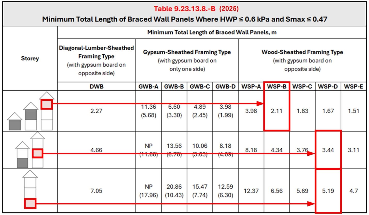
We chose this example because many builders in British Columbia, where this is already a code requirement, many builders have adopted WSP-B for the top floor and WSP-D for the floor(s) below.
Note that an AHJ may request and review detailed calculations and drawings for each wall independently, so wall designations and resulting braced wall panel lengths should be on those drawings. Also note that framers and suppliers must clearly understand the drawings.
Calculation Method
To use this method, the lowest exterior frame walls must support a roof and no more than 2 floors in a normal-weight building. Heavyweight construction, which refers to buildings with tile roofs, stucco walls or floors with concrete topping, or that are clad with directly applied heavyweight materials, is only permitted to support the roof and 1 floor where the RHWP is greater than 0.6 kPa or the Smax is greater than 0.47.
The following conditions must also be met:
Requirements | Value | Details |
Smax | ≤ 2.6 | This applies to all locations in Table C-3 or found in the CHBA online tool. |
RHWP | ≤1.2 KPa | This applies to all locations in Table C-2 Rough terrain is defined as suburban, urban or wooded terrain extending upwind from the building uninterrupted for at least 1 km |
Max. Wall Height unsupported | ≤ 3.1 | The maximum height that a wall can be built without requiring additional structural support like sheathing or bracing |
The Canadian Wood Council has developed The Wind and Seismic Bracing Calculator to aid with the calculations required under this method.
For a full detailed explanation on how to use this method, refer to the Illustrated Guide: Lateral Bracing Requirements that was developed by BC Housing.
For more information, please contact bilal.el-zaylaa@chba.ca
Additional Info
Download File : Backgrounder_Lateral_Loads_2025-08-07.pdf